Meniscus Stability in Rotating Systems
In future cryogenic upper stages the ability of multiple starts of the engine is required [1, 2]. Centrifugal forces caused by the spinning of the stage could drive the liquid propellant away from the outlet of a Propellant Management Device (PMD) resulting in malfunction of the system [3]. A simplified model of the PMD is studied which includes two parallel disks segmented with radially mounted baffles and a central tube. The stability of the menisci between the disks under the influence of the central tube meniscus are examined with Surface Evolver simulations and drop tower experiments.
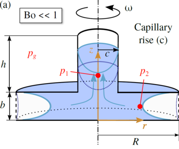
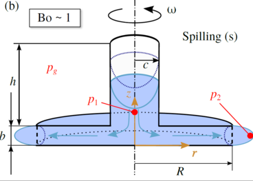
In this study [4] the geometry consists of two parallel disks divided by vertical baffles into n segments. Moreover, in the center of the upper disk a cylindrical tube is added as shown in Figs. 1 and 2. The distance between the disks, the radius of the disks, the radius and height of the central tube are denoted with b, R, c, and h, respectively. Dimensionless parameters are used to investigate the rotating menisci at the edges of the disks and in the central tube. As the length scale the maximum radius of the model R is used. The most important dimensionless parameters are
lengths: b* = b/R , and c* = c/R ,
coordinates: r* = r/R , z* = z/R , and s*= s/R
The origin of the coordinate system is located at the center of the lower disk. An incompressible, perfectly wetting Newtonian liquid is assumed under isothermal conditions. There are menisci in the central tube and between the disks The menisci are analyzed when the model spins at a certain constant angular velocity ω in microgravity (zero gravity). The liquid is assumed to be in a solid-body rotation. This assumption is especially necessary for the analysis of the free surface stability using the Surface Evolver. The dimensionless centrifugal acceleration arot is represented by the rotational Bond number Bo
![]()
with Lc as the characteristic length defined as


For the models two types of instabilities can occur. If an appropriate, i.e. a relatively large aspect ratio of b*/c* is chosen and the value of the Bond number is sufficiently small capillary rise occurs in the central tube due to capillary forces. In Fig.1 this instability is labeled with (c). Moreover, Fig.1 shows that the meniscus or menisci, respectively, if models without or with segments are considered is concave shaped. If Bo is in the magnitude of zero all liquid moves up in the central tube and no stable free surfaces can establish between the parallel disks. For a certain ratio of b* and c* and for Bond numbers larger than zero and below the critical value (0 < Bo < Boc) an equilibrium for the menisci in the tube and between the parallel disks is possible. The instability in Fig. 1 is not considered in the computations with Surface Evolver. However, this type of instability is shown during the drop tower tests. Considering relatively small values of c* and relatively large values of rotation Bo >> 1, i.e. supercritical values of Boc, and zero or microgravity no equilibrium of the menisci can be established as the liquid between the disks spills out of the model (Fig. 2). This causes instability of the meniscus in the tube which is driven outwards in the segments. This instability is denoted as spilling (s). Summarizing the influencing parameters on the stability of the menisci in the tube and between the disks are the rotation Bo, b* and c*. In this work the critical Bond numbers for the menisci between the disks are analyzed as a function of b* and c*. They represent the largest values for Bo before a break-up of these menisci according to Fig. below (b) occurs. The parameters p1 and p2 represent the pressures in the liquid phase at r* = 0 and z* = b*/2. The ambient pressure is labeled pg.
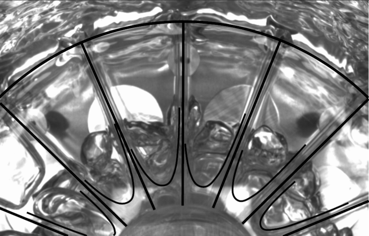
For the computations with the Surface Evolver only the instability "spilling (s)" is considered. In the drop tower tests the other type of instability "capillary rise (c)" occurs as well. Drop tower tests with four other model configuration show inadequate results. It is assumed that the liquid in the model was connected to the bulk liquid in the test cell. This caused an instability of the meniscus in the central tube during reorientation from terrestrial conditions to microgravity. For the drop tower tests the model illustrated in Fig.1 and Fig. 2 is mounted in a cylindrical test tank on a turn table in the drop capsule. The tank diameter is chosen to be 1.75 times of the model diameter. The model is filled with liquid such that distance between the disks is totally filled with liquid and half of the tube is filled with liquid under terrestrial conditions. The rotation of the turn table is initiated 15 minutes prior to each drop to assure solid body rotation. Fig. 3 shows a result for an experiment with a model with n = 16, b* = 0.1, and c* = 0.25. Note that the final configuration of the menisci between the disks, i.e. in the segments, before termination of the experiments is illustrated. The menisci in the segments in this top view are highlighted by black curves.The outer black arc length of a circle and the straight black lines represent the outer edge of the model and the baffles with which the disks are divided into the segments, respectively. It is obvious that for the illustrated drop tower experiment the instability of capillary rise occurs due to a relatively small Bond number of Bo = 0.7736.


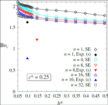
Fig. 4 illustrates the results of the Surface Evolver (SE) (unfilled symbols) computations compared to the results of some drop tower tests (filled symbols). Note that for each drop the setup rotated with a constant angular speed. The notation n = 1 refers to model configuration without segments. All analyzed models have a tube radius of c* = 0.25. Note that the values for the critical Bond numbers for which spilling (s) occurs is smaller in the experiments compared to the results of the SE computations. This can be explained by an insufficient setup for the drop tower tests in which the liquid in the model might have a connection to the bulk liquid in the tank. Due to this connection the liquid in the model was driven out of the model for values below Boc. The drop tower experiments will be repeated with a redesigned setup which will enable to close the free surfaces between the disks such that no liquid will be trapped in the tank prior to the drop.
[1] Behruzi, P., Netter, G.,: Development of a Propellant Management Device (PMD) for Restartable Future Cryogenic Upper Stages, AIAA-2006-5053, pp. 1-10 (2006)
[2] Behruzi, P., Dodd, C., Netter, G.,: Future Propellant Management Device Concepts for Restartable Future Cryogenic Upper Stages, AIAA-2007-5498, pp. 1-10 (2007)
[3] Reichel, Y., Dreyer, M.E.,: Analysis of Critical Disturbances for Propellant Management Devices in Future Cryogenic Upper Stage, AIAA 2011-6063, pp.1-16 (2011)


 "
"