CCF on ISS
Capillary Channel Flow (CCF) is a versatile experiment for studying a variety of inertial-capillary dominated flows key to spacecraft systems that cannot be studied on the ground. Applications of the results of CCF are directed to the portion of the aerospace community challenged by the containment, storage, and handling of large liquid inventories (fuels, cryogens, water) aboard spacecraft. The results are immediately useful for the design, testing, and instrumentation for verification and validation of liquid management systems of current orbiting, design stage, and advanced spacecraft envisioned for future lunar and Mars missions. The results will also be used to improve life support system design, phase separation, and enhance current system reliability.
The experiments are scheduled for the year 2010 onboard the International Space Station (ISS).
Objective:
♦ To enable design of spacecraft tanks that can supply gas-free propellant to spacecraft thrusters, directly through capillary vanes, significantly reducing cost and weight, while improving reliability.
Relevance/Impact:
♦ The current design of spacecraft fuel tanks rely on additional reservoirs to prevent the ingestion of gas into the engines during firing. This research is required to update these current models, which do not adequately predict the maximum flow rate achievable through the capillary vanes eliminating the need to over design tanks.
Realisation of the CCF Experiment:
Forced liquid flows through open capillary channels with free liquid surfaces will be investigated in the Microgravity Science Glovebox (MSG, Figure 1) onboard the International Space Station (ISS) . If a certain critical flow is exceeded, the flow does not remain steady, the surfaces collapse, and gas ingestion occurs at the outlet.
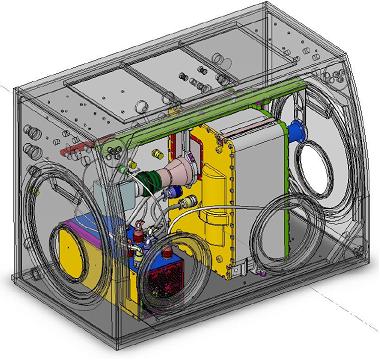
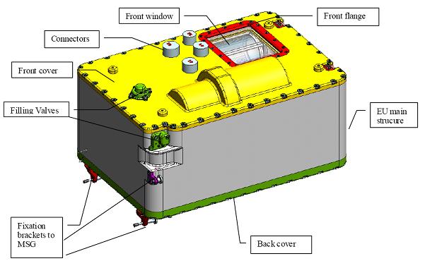
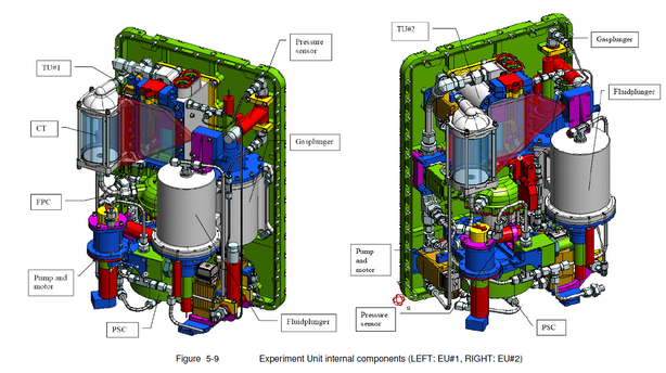
To achieve a high degree of flexibility, the experiment was designed as a modular system consisting of the Fluid Management System (FMS), the Board Computer (BC), and two Experiment Units (EU, Figure 2,3), including Test Units (TU). For the investigation of the selected channel geometries (parallel channel, groove channel, wedge-shaped channel, and a liquid bridge) and different channel dimensions, the TU is exchangeable. This enables the use of the set-up for other projects with similar technology driven research objectives. Furthermore, TU2 includes a gas bubble generator to test two phase flow stability.
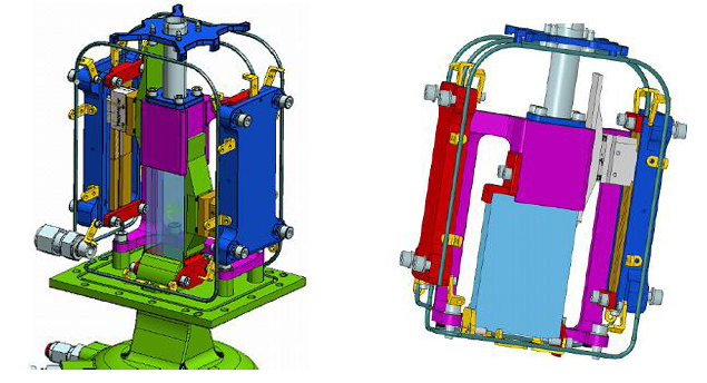
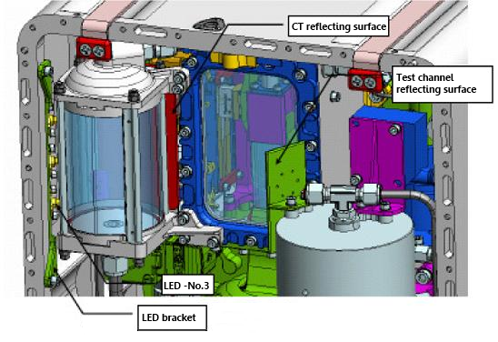
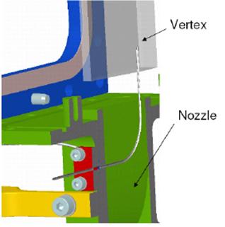
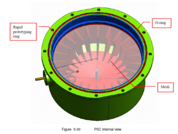
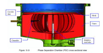
The FMS is equipped with the required components to establish the flow (pumps, plunger, valves), while the EU contains the test channel (Figure 4), a phase separation chamber, (PSC, Figure 5), a compensation tube (CT), cameras for the video observation as well as the required illumination.
The experiment control, the sampling of the housekeeping data as well as the communication with the MSG interfaces and the ground station (PI site) is performed by the BC. For the investigation of the selected channel geometries (parallel channel, groove channel, wedge-shaped channel) and the different channel dimensions, the EU is exchangeable. This enables the use of the set-up for other projects with similar technology driven research objectives.


 "
"